Cemb Hofmann UK

Cemb Hofmann UK
UK Specialist In Balancing Machine Sales & Contract Balancing

Sunday 15 December 2013

Balancing Tolerances and Balancing Planes

Let us consider a rotor having a pure couple unbalance of 15 gr mm placed on two different planes with 100 mm distance:


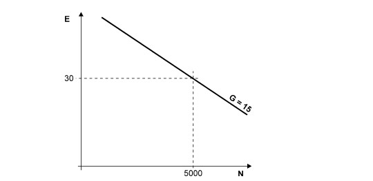
Taking as reference the previous figure, it is clear that, depending on the position (distance ) of the two selected balancing planes, the measured unbalance which is to be corrected varies (30, 15, 10 gr mm).

If the acceptable balancing value per plane is 15 gr mm, then the rotor is considered within tolerance only if the two balancing planes are placed on the supporting position or at a distance of 100 mm; for shorter distances balancing planes the rotor is no more within tolerance.

Now, a rotor should be considered properly balanced (within tolerance ) indifferently of the two selected balancing planes.

As a consequence a correct unbalance tolerance can be specified in two ways by defining:


Defining a limit value (balancing tolerance) for the unbalance referred to the bearing journal directly gives a limitation to the rotating forces which exert on it.

This is particularly useful, because an acceptable residual unbalance calculated with the above mentioned rule, is valid whichever are the two selected balancing planes.

API 612 e 613 standards use this rule and calculate the residual acceptable unbalance with the following formula.


To avoid any confusion between the actual balancing planes (where we act ) and the two planes where the unbalance tolerance is specified.

To specify always, in a clear way, the two planes where the acceptable residual unbalance is valid.

With the use of a modern microprocessor measuring unit, it is possible to specify the tolerance on the two balancing planes or on the two rotor supports.

To specify the unbalance tolerance on the two rotor supports, it is sufficient to set the parameters A = C = 0 and the parameter B = Supports distance


Read more about balancing at the Cemb Hofmann UK site or call our expert balancing team today on 0161 872 3123.

Tuesday 24 September 2013

Static / Couple Unbalance with Narrow Balancing Planes


When balancing on narrow planes, it is necessary to distinguish between static and couple unbalance, because the two types of unbalances have a different effects on the supports.

Example 1: Pure static unbalance


The following figure shows the effects ,on the rotor supports ,generated by a static unbalance applied on a over hang pump impeller.

Support loads are calculated according to the laws of static M = 0 ; R = 0 (The conditions for equilibrium are that the momentum and the resultant of all forces are zero).

Pure Static Unbalance Diagram


Example 2: Couple unbalance


The next figure shows the effect generated by a couple unbalance on the supports of an over hang impeller.


The effect of couple unbalance is reduced by the ratio of the arms.


For the above mentioned reason, different values for static and couple unbalances are specified.

For instance:
Static unbalance tolerance = 1 gr mm
Dynamic unbalance tolerance (couple) = 4 gr mm per plane

For instance:
For axial fun impeller (width 30÷40 mm and an external diameter of 300÷400 mm) the normal required tolerance on the static unbalance is  30÷50 gr mm while a couple unbalance of 100÷200 gr mm is accepted.


Monday 16 September 2013

Allocation of Permissible Residual Unbalance To Each Correction Plane According to ISO 1940/1


ISO 1940/1 standards calculate the total acceptable unbalance of a rotor (static unbalance) referred to the plane (rotor section) containing the centre of mass.

The acceptable residual unbalance on the two balancing planes (dynamic unbalance) is calculated taking care of the position of the centre of mass with regard to the position of the correction planes.


Balancing Diagram


Note:
 
If the calculated value for U1 , U2 is lower than 0.3 Ut  the value 0.3 Ut  is used ; if the calculated value is bigger than 0.7 Ut  the value  to be used is 0.7 Ut,
 
Balancing Diagram from Cemb Hofmann UK


A frequent application of the above mentioned rules happens with pump and fun impellers (over hang mounted.)


For more information about balancing visit Cemb Hofmann UK today or call our expert team on 0161 872 3123.


Tuesday 27 August 2013

Balancing tolerances calculated according to the maximum admitted load on the bearings


The goal of balancing is to reduce loads /vibrations on the supporting frames, in order to achieve an acceptable life.

The unbalance introduces internal couples and rotating forces on the bearings.  As a consequence, the residual acceptable unbalance can be calculated by stating a maximum acceptable value for the rotating (centrifugal forces) generated by the unbalance in service conditions.

A possible rule is to state that the rotating force is kept below 10 percent of the static load.(USA navy standards)

Dynamic and static balancing machine expert


It is worth pointing out that according to API and to ISO standards, the accepted residual eccentricity (unbalance) varies with the relationship is linear while with the last rule (USA navy standards ) it varies with the inverse of the square of the speed (as the speed increases the accepted residual unbalance decreases rapidly.)

If you would like to speak with a balancing expert then call Cemb Hofmann UK today on 0161 872 3123 to discuss any area of unbalance that you may be experiencing with your rotating parts.


Sunday 11 August 2013

Balancing Tolerances according to API 610 Standards


The following formula is valid:


Where:

U [gr mm] = Admitted residual unbalance referred to the bearing journals

W [kg] = Static load on the considered bearing(mass)

N [RPM] = Maximum service speed

Modifying previous formula , we obtain:


The equivalent ISO formula is :


 Important notes:

1) Unbalance tolerance according to API standards is more severe than ISO grade G=1. It is 1,5 more precise and it seems sometimes not obtainable.

2) It is important to point out that the required tolerance, according to API standards, is referred to the bearing journals and not to the two balancing planes. (I will be blogging further about this later this month)

3) The unbalance tolerance measured in microns, (Eccentricity = unbalance per unit of mass) is related to the required mechanical precision , especially when adapters are necessary to mount the rotor on the machine spindle.(the used adapter shall have a mounting precision below the required tolerance

4) For balancing qualities equal to or below G 1 ISO, standard recommends to balance the rotor complete with its own bearings .(The eccentricity between the inside and the outside bearing race can be of the same level as the requested eccentricity).

I will be blogging again shortly to explore "Balancing tolerances calculated according to the maximum admitted load on the bearings".

In the meantime, feel free to contact Cemb Hofmann UK on 0161 872 3123 should you have any specific questions about balancing.

We specialise in dynamic and static balancing as well as the provision of an outstanding sub contract dynamic balancing service from Cemb Hofmann UK

 As a manufacturer of some of the most high precision and accurate balancing machines on the market today, Cemb Hofmann UK is extremely well placed to offer advice on any area of unbalance - from industrial to agricultural and avionic.

Wednesday 31 July 2013

Evaluation of the balancing quality G (The total residual unbalance is known)


In the assumption that the total residual unbalance is known, it is possible to calculate the corresponding value for the balancing quality G according to ISO standards 1940/1.
 

Example of calculation:
 

Rotor mass M [kg] = 6

Maximum service speed N [RPM] = 5000 

Total residual unbalance U [gr mm] = 180 

Total residual eccentricity E [m] = 180/6 = 30


Using the diagram featured in my recent blog post entitled "Balance quality grades for various groups of representative rigid rotors" -  two lines are drawn; one line, normal to the x axis, passing through the maximum service speed value, (5000 in the example).  The second line, normal to the y axis, passing through the residual eccentricity (30 in the example).

The inclined line, passing through the intersection point of the two drawn lines, defines the balancing  quality (grade). 


As an option, the following formula can be used:


If you would like to know more about any area of balancing - or have a specific issue of unbalance that you would like to discuss with an expert, please do not hesitate to pick up the phone and contact Cemb Hofmann UK today on 0161 872 3123 or visit our Cemb Hofmann UK Website now.

Cemb Hofmann is the UK specialist in static and dynamic balancing - manufacturing high precision and highly accurate static and dynamic balancing machines as well as a highly acclaimed sub contract dynamic balancing service.


Tuesday 16 July 2013

Examples of calculation of residual unbalance according to ISO 1940/1 Standards for rigid rotors


Example Number 1: Fun impeller 


Maximum service speed = 1500 RPM

Mass M = 200 kg

Left, right side correction radius Rs = Rd = 800 mm

Balancing quality G = 6,3

From previous diagram we obtain: 

Total acceptable residual eccentricity et = 40 m

Total acceptable residual unbalance Ut = M·e = 200 kg x 40 m = 8000 gr x mm


Note: The acceptable unbalance per plane has been calculated by simply dividing by two the total acceptable unbalance; this operation is correct because the two balancing planes have almost the same distance from the centre of mass position, which is at the same time almost in the centre of the rotor.


Example Number 2:  Turbine


Maximum service speed = 3000 RPM
Rotor mass M = 500 kg
Left side balancing radius Rs = 500 mm
Right side balancing radius Rd = 400 mm
Balance quality G = 2,5
 
From previous diagram we obtain:

Total acceptable residual eccentricity et = 8u


Values within brackets are valid for the quality  G = 1 (quality  g 1 is nowadays commonly required for turbines )


Example Number Three:  Impeller of a centrifugal pump 


Maximum service speed = 6000 RPM
Mass M = 10 kg
Balancing radius R = 100 mm
Required balancing quality G = 6.3

From previous diagram we obtain:


Note: Since the impeller is thin (reduced axial dimensions ) it is balanced in one plane only ( Static balancing)


Example Number 4:  Tool holder dynamically balanced 


The tool holder has a useful length L bigger than 2D (where D is the cone diameter ).

Considering its length it is advisable to balance it on two planes.

Maximum service speed = 24'000 RPM

Tool holder mass M = 5 kg

Correction radius on balancing plane 1 R1 40 mm

Correction radius on balancing plane 2 R2 20 mm

Required balancing quality G = 2.5

(ISO standards specify quality G=2.5 for machine tools spindles and driving systems)

Total acceptable residual eccentricity E = 1 m

Total acceptable residual unbalance Ut = M·E = 5 kg x 1 m = 5 gr x mm


Note: The total acceptable unbalance has been divided by two because we assumed that tool holder mass is more or less symmetrical with regard to the centre of mass position ,and that the two correction planes contain the centre of mass almost in the middle position.

Example Number 5:  Tool holder balanced in one plane only


Let us consider a tool holder which is to be balanced in one plane (static balancing).

Normally the tool holder is balanced in one plane only , if its length L is lower than 2D (D is cone diameter)

Maximum service speed = 12'000 RPM
 
Tool holder mass M = 1 kg

Balancing radius = 20 mm

Balancing quality G = 1

(ISO standards specify quality G 1 for grinding machine spindles)

Total acceptable eccentricity E = 2 m

Total acceptable residual unbalance Ut = M·E = 1 kg x 2 m = 2 gr x mm 


Cemb Hofmann UK is the leading UK Balancing expert and offers not only high precision balancing machine sales but also a highly acclaimed sub contract dynamic balancing service. 

For more information about any area of balancing, please visit the Cemb Hofmann UK Website or call us today on 0161 872 3123.


Wednesday 19 June 2013

Understanding Required Balancing Tolerances


The following drawing defines the required balancing tolerance according to  ISO 1940/1.standards:


NOTE: The table in my previous blog defines the required balancing quality G according to each rotor type.

The maximum service speed is reported on the horizontal x axis , while the acceptable specific unbalance (acceptable unbalance per unit of mass or acceptable residual mass eccentricity ) is reported on the vertical y axis.

The following formula can be used instead of the previous diagram:

Where: Et [] = total acceptable mass eccentricity
N [RPM] = Maximum service rotor speed
G [mm/s] = Balancing quality or grade
Total residual accepted unbalance: U [gr∙mm] = Et∙M
where: M [kg] = Rotor mass
Total residual admitted unbalance in grams is  where R [mm] is the compensation radius.

This is all very technical stuff and most likely, only of interest to a very small number of people who enjoy the complexities of balancing as much as myself!

If you would rather leave the formulae to the experts then why not have a chat with a balancing machine expert at Cemb Hofmann UK.

Call us today on 0161 872 3123 and we will be delighted to assist you with whatever area of unbalance you are experiencing with your rotating parts.


Tuesday 18 June 2013

A Guide to Balance Qualilty Grades

The chart below is designed to give an overview of the balance quality grades for various groups of representative rigid rotors.

Note:  Some groups of rotors, not included in the official ISO table, are added and reported in Italic type form.

Balancing quality grade is show in G mm/s

-----------------------------------------------------------------------------------

0,4    Gyroscopes
         Spindles, discs and armatures of precision grinders
         Textile fuses

1,0    Small electric armatures with special requirements
         Tape recorder and phonograph (gramophone) drives, cine projectors
         Grinding machine drives
         Turbines  and Compressors with special requirements

2,5    Gas and steam turbines, including marine main turbines  (merchant service)
         Turbine driven pumps
         Rigid turbo generator rotors
         Turbo compressors
         High speed compressors and aeronautic compressors
         Medium and large electric armatures with special requeriments
         High quality household electric armatures, dentist drills and textile components
         Small electric armatures not qualifying for one or both of the conditions specified
         for small electric armatures of balancing quality grade G 6,3
         Machine tool drive
         Air conditioning fans for hospitals and concert halls
         High speed gears(over 1000 RPM) of marine turbines .

         Computer memory drums and discs

6,3    Small electric armatures, often mass produced, in vibration insensitive applications, and/or
          with vibration isolating mountings.
          Medium and large electric armatures (of electric motors having at least 80 mm shaft height )
          without special requirements
          Machine tool and general machinery parts
          Parts of process plant machines, Centrifuge drums, decanters, washers
          Hydraulic machine rotors

          Fly wheels, Fans; Pump impellers
          Marine main tuebine gears (merchant service )
          Paper machinery rolls; print rolls
          Assembled aircraft gas turbine rotors
          Individual components of engines under special requirements

16      Drive shafts (propeller shafts, cardan shafts) with special requirements
          Parts of agricultural machinery, parts of crushing machines
          Individual components of engines (gasoline or diesel) for cars ,trucks and locomotives
          Crankshaft / drives of engines with six or more cylinders under special requirements
          Low speed separators
          Light boat impellers)
          Motor bicycle and car wheels
          Normal transmission pulley
          Wood machine tools


40      Car wheels, wheel rims, wheel sets and drive shafts
          Crankshaft / drives of elastically mounted fast four cycle engines (gasoline or diesel ) with
          six or more cylinders (pistons speed greater than 9 m/s)
          Crankshaft /drives of engines of cars , trucks and locomotives

We hope that you will find this information useful - please get in touch with the specialist balancing team at Cemb Hofmann UK on 0161 872 3123 should you have any queries regarding this table or any other aspect of balancing.

Please visit our site: www.cembhofmann.co.uk for more information about balancing machines and sub contract balancing services.


Monday 10 June 2013

Balancing Tolerances

The balancing of a rotating body has different goals:

1) Reduced load on the bearings (low centrifugal forces)
2) Long bearings life
3) Acceptable vibration levels (a good vibration level does not create any problems to the comfort or to component life.

From previous point 3 , it is clear that the optimum value for the residual unbalance can be evaluated in an experimental mode, by considering that:

a) The inertia force generated by the unbalance can be calculated using the formula reported on paragrath 1.15

b) On service vibrations, levels can be easily measured with a simple vibrometer.
For each application an acceptable value for the admitted residual unbalance (which grants good performances ) can be defined.

ISO 1940 standards gives a rule in order to calculate an acceptable residual unbalance, having following features:

1) Gross unbalance deficiencies are avoided,
2) Useless and excessive balancing works are avoided


Where:    E = Mass eccentricity [microns]
                U = Unbalance [gr•mm]
                M = Rotor mass [kg]

According to ISO 1940 standards, all rotors are classified (grouped), depending on their balancing requirements (look at following table). Balancing quality G is a number which defines the balancing accuracy required; for instance G = 2,5 means that a fine balancing is required, G = 6,3 means that a normal balancing is accepted.

Please note that the measuring unit for  G is mm/s, because this value represents the vibration speed assumed by the body rotating freely in the space at the real service speed.

The same value of vibration speed ( G=mm/s) is achieved by the rotor, when it rotates mounted on a soft bearing machine at service speed.


Balancing can be a very complex subject and I would be delighted to hear from anyone experiencing unbalance who is in need of technical advice.

Cemb Hofmann is the UK's leading specialist in balancing - from balancing machine sales to a world-class sub contract dynamic balancing service.

Visit www.cembhofmann.co.uk today for more information or call us on 0161 872 3123 to speak to a member of our team today.


Tuesday 14 May 2013

The Common & Frequent Words of Balancing

Balancing is a complex and tricky artform - producing a technical language that is riddled with certain phrases and words that would confuse many customers in need of balancing advice.

Below is an explanation of two of the most common used terms.

Static balancing :  Unbalance measuring and correction is carried out in one plane only.

Dynamic balancing :  Unbalance measuring and correction is carried out in two different planes.

Correction planes :  Is the section (plane) where unbalance correction is performed by adding or removing mass.

static and dynamic balancing


At Cemb Hofmann we pride ourselves in the delivery of first class balancing services - from high quality machine sales to a world-class sub contract balancing service.

To find out more visit www.cembhofmann.co.uk or call our team today on 0161 872 3123

Balancing Speed: A Comprehensive Explanation

The unbalance of a rotor is caused by the radial distribution of its masses along its axis of rotation.

The consequence is that if the rotor is rigid, and this means that the values and relative positions of its masses do not change, the unbalance does not change with the speed. In a rigid rotor the operating speed does not modify mass distribution and consequently has no influence on the unbalance.

By adding a 20 gr mass at a defined radial position on a perfectly balanced disc an unbalance is generated. This unbalance does not change with the speed, it is just necessary to remove the added 20 gr mass independently of rotor speed.

For rigid rotors the balancing speed does not need to be specified because it is related only to machine sensitivity and not to the rotor unbalance which is under measurement.

Modern hard bearing balancing machines have the capability to measure the dynamic unbalance starting from 70 RPM.

The unbalance effect (centrifugal force) increases with speed, the electric signal increases at the same time and so machine sensitivity tends to increase because of a better ratio signal to noise.
Depending on the model and manufacturer optimum sensitivity values are obtainable starting from 400 to 600 RPM.

Note: don’t get confused between the cause (unbalance) with its effect (centrifugal force or vibration).

The effect increases with the speed while the cause (unbalance) in a rigid body does not change.

For further information about any aspect of balancing please visit www.cembhofmann.co.uk or call our expert team today on 0161872 3123.

Friday 26 April 2013

Dynamic Balancing


Dynamic balancing a rotor means to reduce its dynamic unbalance to zero or to an acceptable level.

This process will eliminate costly and sometimes irrepairable damage to the unit and is absolutely essential to the maintenance and quality of rotating parts.
 
The dynamic unbalance is by definition:
 
Dynamic balancing


So it is necessary to operate on two different planes.
 
Since the dynamic unbalance equivalent ot the total unbalance Ut can be calculated with reference to two arbitrary planes, the consequence is that thte two balancing planes (where material can be added or removed) can be chosen.
 
The above is valid for rigid rotors where mass distribution (local unbalances) does not vary with the speed.
 
 
In order to balance with the minimum effort two rules are valid:
 
 
1)  Choose balancing planes as far apart as possible
 
2)  Choose a balancing radius as large as possible
 
 
Note: by the dynamic balancing on two different planes the total unbalance (set of local unbalances) is not reduced to zero; only the dynamic unbalance (on two planes ) equivalent to the total unbalance Ut is reduced to zero.
 
 
 Discover more about dynamic balancing by visiting the Cemb Hofmann resource centre or call our expert balancing team on 0161 872 3123.


Thursday 4 April 2013

Couple Unbalance

A Definition of Couple Unbalance


The total unbalance is called couple unbalance if the equivalent unbalance is made by two vectors placed on two different planes having equal values and opposite directions.

 (The axis of inertia cuts the axis of rotation passing through the centre of mass)

Balancing Machines and Services
 
 
Of course values Us and Ud (unbalance value in the two sections) are equal.
 
For example: if the declared couple unbalance value is 6000 gr.cm.cm and the distance between the two balancing planes is  15 cm, then the unbalance per plane is  6000/15 =400gr.cm (4000 g.mm ). If the balancing radius on each plane is 20 cm, then the unbalance per plane is 400/20=20grams (the two unbalances on each plane are equal in value but opposite in the angle position)
 
For more information on balancing or sub contract dynamic balancing services, please call our expert today on 0161 872 3123 or visit the Cemb Hofmann UK site.


Static Balancing

A definition of static unbalance


The total unbalance is called static if it is equivalent to a single unbalance vector placed in a section which also contains the centre of mass of the rotor.

(The axis of inertia is parallel to the axis of rotation)


Static Balancing Machines 


If the equivalent vector is not located in one section containing also the centre of mass we call it quasi-static unbalance.

In practice most people call static unbalance the total equivalent unbalance when it is placed in a single plane only.

Cemb Hofmann specialise in static balancing machines and our expert team will be delighted to guide you through our balancing processes - from professional balancing machines to sub contract balancing services.

Call us now on 0161 872 3123 or visit the Cemb Hofmann UK site today.

Thursday 21 March 2013

A Definition of Unbalance

None uniform mass distribution around the axis of rotation


A Rotor is unbalanced when its mass is not evenly distributed around the axis of rotation
From definition it is clear that it makes no sense to speak of unbalance without defining the axis of rotation, that is the ideal line around which the mass distribution is considered.

Balancing resources from Cemb Hofmann UK

Every rotor can be divided into different sections (perpendicular to the axis of rotation) each one having its own unbalance.

When in rotation, a rotor experiencing unbalance will want to revolve around its mass centre axis and because this motion is restricted by bearings, the resulting centrifugal fource will cause excessive vibration.

This vibration can be catastrophic - creating unnecesary wear to bearings and more noise.

If the correct action is not taken to address unbalance, the result can be as dramatic as a total breakdown of the rotor.

Therefore, if you would like to speak to a balancing expert - get in touch with  Cemb Hofmann UK on 0161 872 3123 today.

We have extensive expertise in this field, from dynamic balancing services to machine sales and even training course - we will be delighted to talk you through the right approach to correcting whatever unbalance your machinery parts may be experiencing.

Thursday 7 March 2013

Balancing Rotors


Balancing Rotors: The Basic Principles

Balancing requirements

Unbalance control and measurement of rotating bodies is becoming more important for different reasons: 

1) Higher operating speeds (more production) 

2) Lighter construction (lower production costs) 

3) Service speeds near to critical speeds (technical or space reduction does not allow more rigid construction) 

4) Longer component life (bearings for instance) 

5) Lower maintenance costs (for repair and component exchange)  

6) Longer machine availability (fewer production stoppages)
 

It is important to point out that the measurement of unbalance is a quality control process at the end of manufacture or production line. It reveals errors on dimension tolerances, casting faults, uneven parts and is an index for the quality of the final product. 


A Definition Of Unbalance


None uniform mass distribution around the axis of rotation 


A Rotor is unbalanced when its mass is not evenly distributed around the axis of rotation

From definition it is clear that it makes no sense to speak of unbalance without defining the axis of rotation, that is the ideal line around which the mass distribution is considered.

 
A definition of unbalance


Every rotor can be divided into different sections (perpendicular to the axis of rotation) each one having its own unbalance. 

I will be blogging with more information about couple, static and dynamic unbalance over the next few weeks so please feel free to ask any questions in the meantime - if you are experiencing a particular aspect of ubalance then Cemb Hofmann UK can most certainly be of service.
 
If you want to find out more about any aspect of balancing just visit our site!